Connecting the CC2530
Pin layouts
The pin layout is different between each CC2530 module
| Name | Pin layout | Picture |
|---|---|---|
| CC2530 | 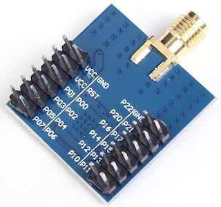 |  |
| Webee CC2530 + CC2591 | 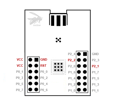 |  |
Using a USB to serial adapter
Confirmed working
This how-to has been confirmed working with the following CC2530 based devices:
| Device | Image |
|---|---|
| CC2530 | |
and the following USB to serial adapters:
| Device | Image |
|---|---|
| CP2102 | 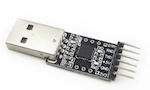 |
Flashing the firmware
The required coordinator firmware can be found here: Zigbee 1.2 and Zigbee 3.0.
Connecting
Connect to CC2530 to the USB to serial adapter using the following mapping:
| USB-Serial Adapter | CC2530 |
|---|---|
| 3V3 | VCC |
| GND | GND |
| TXD | P02 |
| RXD | P03 |
Now plug in the USB-to-serial adapter in your USB port and start Zigbee2MQTT, enjoy!
To a Raspberry Pi (Zero)
CC2530 can be connected to a Raspberry PI (Zero) via GPIO Pins - no USB2FTDI is needed.
The use of UART by the installed Linux has to be disabled: Detailed explanation here
Enable UART in the Kernel and disable UART use for BlueTooth.
In /boot/config.txt add following lines:
enable_uart=1
dtoverlay=pi3-disable-bt
Disable the modem system service (on the command line):
sudo systemctl disable hciuart
Remove the console entry by removing any of those entries from /boot/cmdline.txt if present:
console=serial0,115200 console=ttyAMA0,115200
Reboot your Raspberry.
Wiring CC2530 to the Raspberry
CC C2530 -> Raspberry
VCC -> 3,3V (Pin1)
GND -> GND (Pin6)
P02 -> TXD (Pin8 / BCM 14)
P03 -> RXD (Pin10 / BCM 15)
Configuring Zigbee2MQTT
Change the Serial Port in your data/configuration.yaml file:
serial:
  port: /dev/ttyAMA0
Have fun.
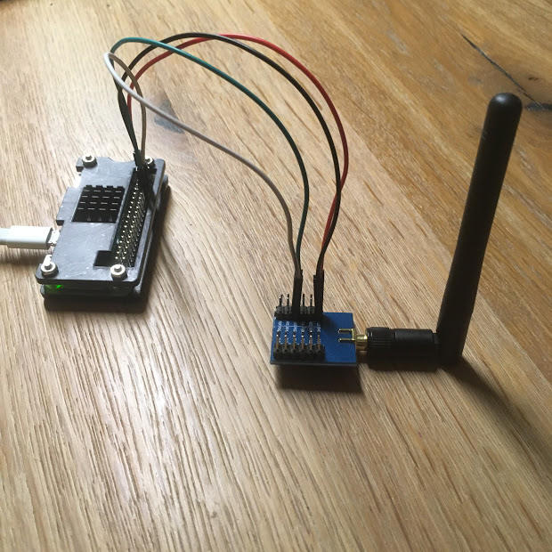
Via an ESP8266 as a serial to WiFi bridge
This setup allows you to connect a CC2530 to an ESP8266 which can be put everywhere in your house. Via a serial socket, Zigbee2MQTT will connect to your CC2530.
Wiring
Wire the CC2530 to the ESP8266 using the following scheme:
| ESP8266 | CC2530 |
|---|---|
| 3v3 | VCC |
| GND | GND |
| TX | P02 |
| RX | P03 |
| GND | P20 |
| GND | P04 |
| GND | P05 |
Option 1 - Flashing the ESP8266 with ESPEasy
The ESP8266 needs to be flashed with ESPEasy. ESPEasy has sufficient documentation on how to get you up and running:
- How to flash the ESP8266 with ESPEasy
- ESP8266 firmware: ESP_Easy_mega-XXXXXXXX_normal_ESP8266_4096.bin
- More information about ESPEasy
Setting up ESPEasy
Open the ESPEasy web interface and complete the setup. Afterwards open the web interface again.
Click on Devices Edit of the first task and select Communication - Serial Server from the dropdown list.
Fill in the form as following:
a.    Name: ZIGBEE2MQTT
b.    Enabled: checked
c.    TCP Port: a number between 1000 and 9999 "1775"
d.    Baud Rate: 115200
e.    Data bits: 8
f.    Parity: No Parity
g.    Stop bits: 1
h.    Reset target after boot: - none –
i.    RX receive timeout: 0
j.    Event processing: Generic
Press Submit, the setup is now completed.
Option 2 - Flashing the ESP8266 with Tasmota
The ESP8266 needs to be flashed with Tasmota firmware, "zbbridge" build. Please find flashing instructions in the following guides:
You don't need MQTT for the serial to network functionality but it is a nice option to monitor your bridge.
Setting up Tasmota
Open the Tasmota web interface and complete the basic network setup. Next in "Configuration", "Configure Module" define your RX and TX pins. The Rx/Tx are relative to the ESP device. For example with ESP8266/ESP01's hardware serial, set GPIO1 as TCP Tx and GPIO3 as TCP Rx.
Next, in Tasmota's main screen, open "Console". Enter TCPBaudRate 115200. Decide on the port number to use and set it. For example for port = 8888 run:
Rule1 ON System#Boot do TCPStart 8888 endon
Rule1 1
Zigbee2MQTT configuration
Now add the following to the Zigbee2MQTT configuration.yaml:
serial:
    port: 'tcp://192.168.2.13:20108'
    adapter: zstack
Note to change the IP address and port. You can now start Zigbee2qmtt.